Search
materials and coatings
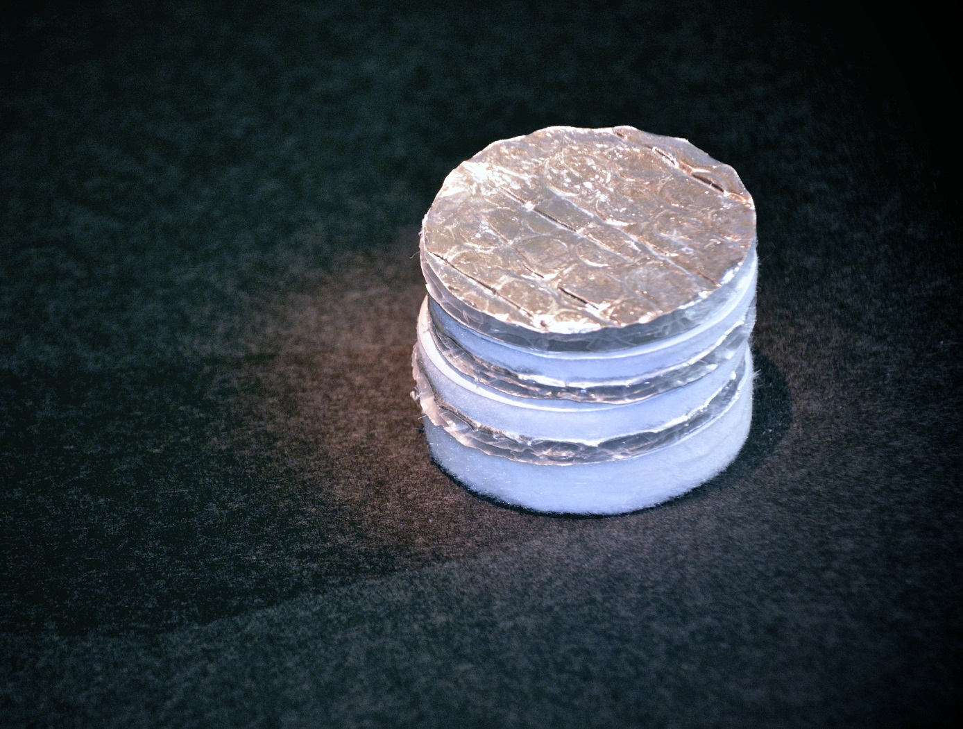
Layered Composite Insulation for Extreme Conditions (LCX)
The approach in developing the LCX system was to provide a combination of advantages in thermal performance, structural capability, and operations. The system is particularly suited for the complex piping, tanks, and apparatus subjected to the ambient environment common in the aerospace industry. The low-cost approach also lends the same technology to industrial applications such as building construction and chilled-water piping. The system can increase reliability and reduce life cycle costs by mitigating moisture intrusion and preventing the resulting corrosion that plagues subambient-temperature insulation systems operating in the ambient (humidity and rain) environment. Accumulated internal water is allowed to drain and release naturally over the systems normal thermal cycles. The thermal insulation system has a long life expectancy because all layer materials are hydrophobic or otherwise waterproof. LCX systems do not need to be perfectly sealed to handle rain, moisture accumulation, or condensation.
Mechanically, the LCX system not only withstands impact, vibration, and the stresses of thermal expansion and contraction, but can help support pipes and other structures, all while maintaining its thermal insulation effectiveness. Conventional insulation systems are notoriously difficult to manage around pipe supports because of the cracking and damage that can occur. Used alone or inside another structure or panel, the LCX layering approach can be tailored to provide additional acoustic or vibration damping as a dual function with the thermal insulating benefits. Because LCX systems do not require complete sealing from the weather, it costs less to install. The materials are generally removable, reusable, and recyclable, a feature not possible with other insulation systems. This feature allows removable insulation covers for valves, flanges, and other components (invaluable benefits for servicing or inspection) to be part of original designs.
Thermal performance of the LCX system has been shown to equal or exceed that of the best polyurethane foam systems, which can degrade significantly during the first two years of operation. With its inherent springiness, the system allows for simpler installation and, more importantly, better thermal insulation because of its consistency and full contact with the cold surface. Improved contact with the cold surface and better closure of gaps and seams are the keys to superior thermal performance in real systems. Eliminating the requirement for glues, sealants, mastics, expansion joints, and vapor barriers provides dramatic savings in material and labor costs of the installed system.
communications
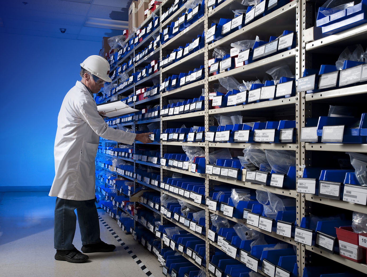
Smart Enclosure using RFID for Inventory Tracking
The smart enclosure innovation employs traditional RFID cavities, resonators, and filters to provide standing electromagnetic waves within the enclosed volume in order to provide a pervasive field distribution of energy. A high level of read accuracy is achieved by using the contained electromagnetic field levels within the smart enclosure. With this method, more item level tags are successfully identified compared to approaches in which the items are radiated by an incident plane wave. The use of contained electromagnetic fields reduces the cost of the tag antenna; making it cost-effective to tag smaller items.
RFID-enabled conductive enclosures have been previously developed, but did not employ specific cavity-design techniques to optimize performance within the enclosure. Also, specific cavity feed approaches provide much better distribution of fields for higher read accuracy. This technology does not restrict the enclosure surface to rectangular or cylindrical shapes; other enclosure forms can also be used. For example, the technology has been demonstrated in textiles such as duffle bags and backpacks. Potential commercial applications include inventory tracking for containers such as waste receptacles, storage containers, and conveyor belts used in grocery checkout stations.
Sensors

Optical Mass Sensor for Multi-Phase Flows
Unlike commercial turbine and Venturi-type sensors, which are flow intrusive and prone to high error rates, NASA's new flow sensor technology uses an optical technique to precisely measure the physical characteristics of a liquid flowing within a pipe. It generates a reading of the flows density, which provides a highly accurate mass flow measurement when combined with flow velocity data from a second optical sensor.
NASA's sensor technology provides both a void fraction measurement, which is a measurement of the instantaneous gas/liquid percentage of a static volume and a quality measurement, which is the fraction of flow that is vapor as part of a total mass flow. It also provides a direct measurement of the gas/liquid concentration within the flow, making it suited for real-time measurement of multi-phase flows.
The technology was originally developed to accurately determine the flow rates and tank levels of multi-phase cryogenic fuels used on various NASA vehicles including the Space Shuttle and in ground-based propulsion testing. It can also be used for a wide range of gas/liquid ratios, flows with complex cross sectional profiles, flows containing bubbles or quasi-solids, and essentially any liquid, gas, or multi-phase flow that can be optically characterized. Because it is insensitive to position, the new technology also has potential for use in zero-gravity tank level sensors.
sensors

Fluid Measurement Sensor
The fluid measurement sensor is configured with a spiral electrical trace on flexible substrate. The sensor receives a signal from the accompanying magnetic field data acquisition system. Once electrically active, the sensor produces its own harmonic magnetic field as the inductor stores and releases magnetic energy. The antenna of the measurement acquisition system is switched from transmitting to receiving mode to acquire the magnetic-field response of the sensor. The magnetic-field response attributes of frequency, amplitude, and bandwidth of the inductor correspond to the physical property states measured by the sensor. The received response is correlated to calibrated data to determine the physical property measurement. When multiple sensors are inductively coupled, the data acquisition system only needs to activate and read one sensor to obtain measurement data from all of them.
Fluid level measurement occurs in several ways. In the immersion method, the capacitance of the sensor circuit changes as it is immersed in fluid, thus changing the frequency response as the fluid level rises or falls. Fluid level can also be measured from the outside of a non-conductive container. The response frequency from the sensor is dependent upon the inductance of the container plus the combination of fluid and air inside it, which corresponds to the level of liquid inside the container. Roll and pitch are measured by using three or more sensors in a container. With any given orientation, each sensor will detect a different fluid level, thus providing the basis for calculating the fluid angle. Volume can be measured in the same way, using the angle
levels detected by the sensors and the geometric characteristics of the container to perform the volume calculation.
Instrumentation
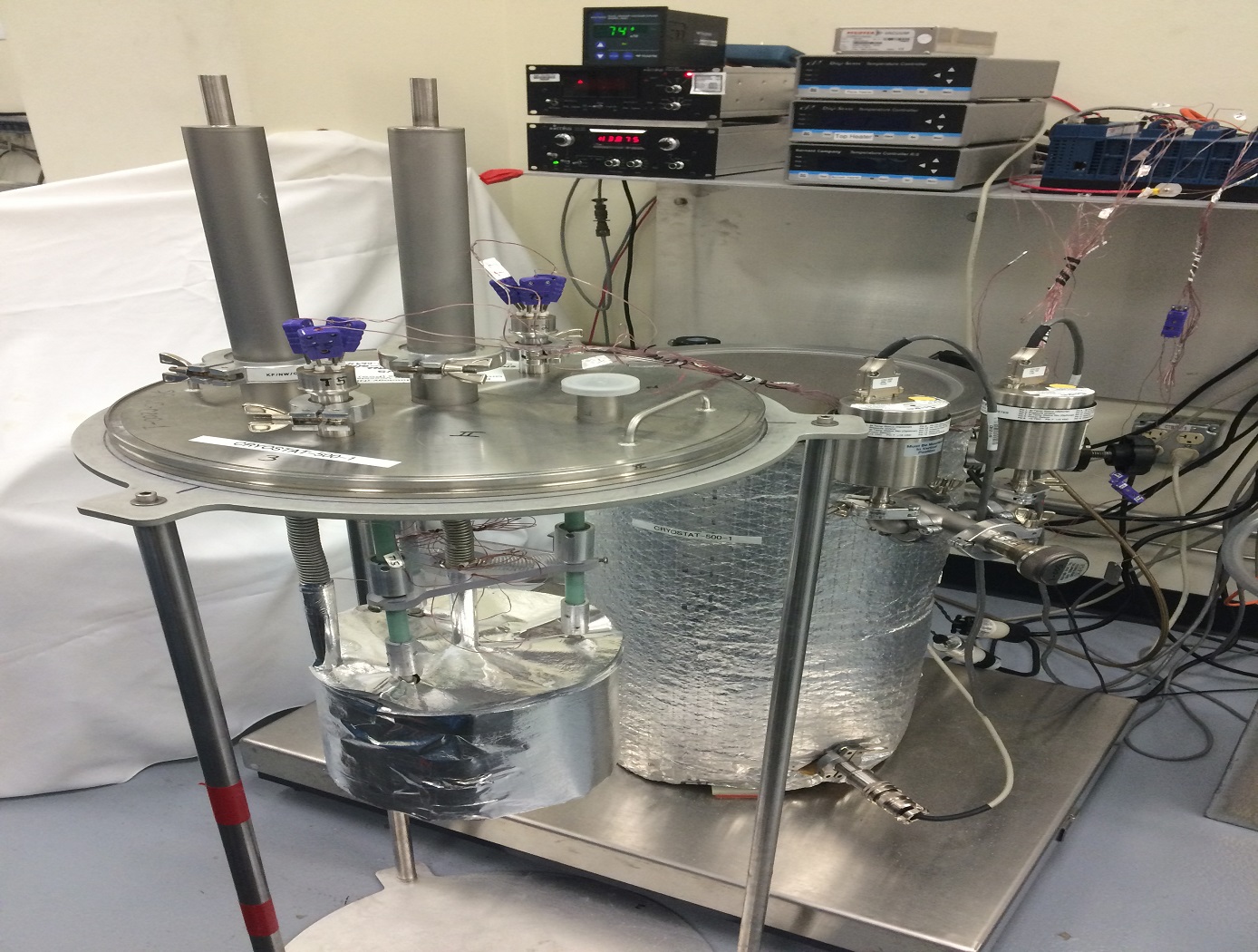
Cryostat-500
The Cryostat-500 provides laboratory measurement of the steady-state thermal transmission properties of thermal insulation systems under conditions below ambient temperature. Liquid nitrogen is used as a direct measure of the energy going through the test specimen. Thermal insulation systems may be composed of one or more materials that may be homogeneous or non-homogeneous at boundary conditions from 77 K to 373 K and in environments from high vacuum (10E-7 torr) to ambient pressure (10E+3 torr).
The Cryostat-500 provides a much wider range of thermal performance and covers the full range of environmental conditions for applications below ambient temperature. The instrument has been proven through extensive testing of foams, composite panels, multilayer insulation (MLI) systems, aerogel blankets, fiberglass, and many other types of materials. Both the quality and quantity of the thermal performance data for insulation materials and systems have increased even as the process and method has become more time efficient and cost effective. Further guidelines on the test method and equipment for the Cryostat-500 are given in ASTM C1774, Annex A3.
materials and coatings
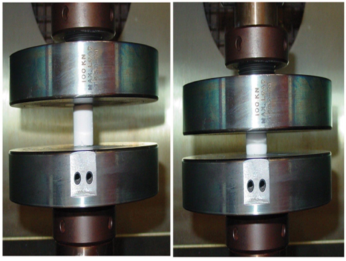
Polymer Cross-Linked Aerogels (X-Aerogels)
Researchers at NASA's Glenn Research Center have developed an approach to significantly improve the mechanical properties and durability of aerogels without adversely affecting their desirable properties. This approach involves coating conformally and cross-linking the individual skeletal aerogel nanoparticles with engineering polymers such as isocyanates, epoxies, polyimides, and polystyrene. The mechanism of cross-linking has been carefully investigated and is made possible by two reactions: a reaction between the cross-linker and the surface of the aerogel framework and a reaction propagated by the cross-linker with itself. By tailoring the aerogel surface chemistry, Glenn's approach accommodates a variety of different polymer cross-linkers, including isocyanates, acrylates, epoxies, polyimides, and polystyreneenabling customization for specific mission requirements. For example, polystyrene cross-linked aerogels are extremely hydrophobic, while polyimide versions can be used at higher temperatures. Recent work has led to the development of strong aerogels with better elastic properties, maintaining their shape even after repeated compression cycling. By tailoring the internal structure of the silica gels in combination with a polymer conformal coating, the aerogels may be dried at the ambient condition without supercritical fluid extraction.
sensors
Streamlined Liquid Level Sensing Using Fiber Optics
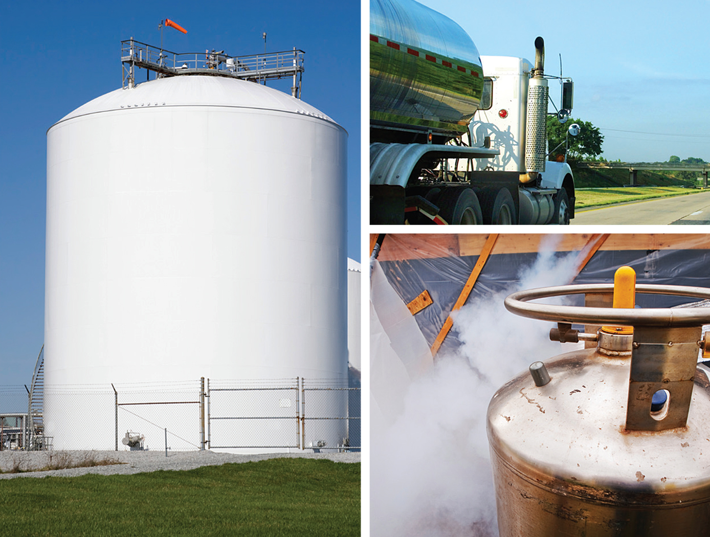
Armstrong has developed a robust fiber optic–based sensing technology that offers extraordinary accuracy in liquid level measurements. The sensing system uses fiber optic Bragg sensors located along a single fiber optic cable. These sensors actively discern between the liquid and gas states along a continuous fiber and can accurately pinpoint the liquid level.
<strong><i>How It Works</strong></i>
The technology uses a resistive heater wire bundled with the optical fiber. The heater is pulsed to induce a local temperature change along the fiber, and the fiber Bragg grating data is used to monitor the subsequent cooling of the fiber. The length of fiber in the liquid cools more rapidly than the portion of the fiber in the gas above the liquid. The measurement system accurately establishes the location of this transition to within 1/4-inch.
<strong><i>Why It Is Better</strong></i>
Armstrong's liquid level sensing technology was originally developed to measure cryogenic liquid levels in rockets, and it represents a significant advancement in the state of the art in this application. Conventional methods for measuring cryogenic liquid levels rely on cryogenic diodes strategically placed along a rod or rack. The diodes are mounted in pre-selected, relatively widely spaced positions along the length of a rod; this configuration provides limited, imprecise data. Furthermore, each diode on the rod has two wires associated with it, which means a single system may require a large number of wires, making installation, connectivity, and instrumentation cumbersome.
Armstrong's novel technology provides liquid measurements with much greater precision, achieving measurements at 1/4-inch intervals. Furthermore, the streamlined system uses just two wires, which greatly simplifies installation and instrumentation. Due to its extraordinary accuracy and ease of use, Armstrong's measurement system offers important advantages for a wide range of applications beyond cryogenic liquids.
<strong><i>In Addition</strong></i>
Researchers have developed a new manufacturing process that improves the ability of fiber optic sensing systems to measure temperature and liquid levels when operating in humid environments. The process involves eliminating moisture from the optical fiber coating, then completing the sensor assembly within humidity-controlled conditions. The resulting sensor hardware provides precise and accurate measurements even when operating in a humid environment.
<b><i>For more information about the full portfolio of FOSS technologies, see DRC-TOPS-37 or visit <a href=https://technology-afrc.ndc.nasa.gov/featurestory/fiber-optic-sensing>https://technology-afrc.ndc.nasa.gov/featurestory/fiber-optic-sensing</a></b></i>


